914-SHO Project Thread

Disclaimer: Links on this page pointing to Amazon, eBay and other sites may include affiliate code. If you click them and make a purchase, we may earn a small commission.

3d914

SHO Member
Joined
Feb 1, 2008
Messages
832
Reaction score
338
Location
Arizona
Wow - it's amazing what can happen when you're off line for a few days! :rofl:

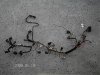
Anyhew - the engine is coming along. Tom's been a big help getting things squared away. We've got a good block, crank, rods, pistons, heads, intake, etc.
I've started cleaning and will begin prepping for paint. This engine is going in a 914 that will be an orange. Here's one of the colors I like - Signal Orange, the other is Tangerine.
image.php


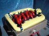
There are two complimentary colors on the car. When racing the GT's the factory would color code the bumpers so that each car could be identified easier when viewed head-on. I plan to apply this to my car and use yellow and red for the two halve-colors on the front & rear bumpers. These are the same colors I'll use for the engine.

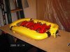
Here's a quick image my son modified for me to illustrate. The block and oil pan will also be yellow to match the intake.
image.php


I wanted to avoid black since the engine cover is a black mesh. This way colors will be more apparent behind the black grill.
 
Last edited:

3d914

SHO Member
Joined
Feb 1, 2008
Messages
832
Reaction score
338
Location
Arizona
Well,

Work has commenced on the engine. The block is assembled and painted & the oil pan is painted. I just started cleaning up the valve covers and dismantling the intake manifold for modification and painting.

There appears to be a coating on the valve covers (don't think its anodziing) - so I need to figure this out and whether it has to be removed completely before painting.

There are several flanges on the intake manifold that I will not be using, as some components will be eliminated or relocated. Starting with the DIS mounting ******.

To remove it I first cut off large sections top & bottom, then started to grind and file down close to the desired shape. I continued to rough the shape with a file, then did some sanding with 60 & 100 grit. The hole will get welded in and then I will finish it all off. But there are several other smaller flanges that need to come off also.
image.php


Gettin there slowly . . .
 
Last edited:

ManySHOs

[]=[] []
Joined
Feb 18, 2001
Messages
1,935
Reaction score
131
Location
South Jersey
Well,

Work has commenced on the engine. The block is assembled and painted & the oil pan is painted. I just started cleaning up the valve covers and dismantling the intake manifold for modification and painting.

There appears to be a coating on the valve covers (don't think its anodziing) - so I need to figure this out and whether it has to be removed completely before painting.

There are several flanges on the intake manifold that I will not be using, as some components will be eliminated or relocated. Starting with the DIS mounting ******.
attachment.php


To remove it I first cut off large sections top & bottom, then started to grind and file down close to the desired shape. I continued to rough the shape with a file, then did some sanding with 60 & 100 grit. The hole will get welded in and then I will finish it all off. But there are several other smaller flanges that need to come off also.
attachment.php


Gettin there slowly . . .

I've found that the best way to remove the paint from the manifold and valve covers is to glass bead them. I highly recommend powdercoating over painting as it will hold up much better.

Are you using the EGR system? If not, you can remove the EGR tunnel on the bottom of the rear surge tank. It takes awhile but it looks so much better once it's gone. I'm really happy with the way mine came out.

Ian
 

jthod

Mr. Goodwrench
Joined
Jun 18, 2007
Messages
2,781
Reaction score
233
Location
Lincoln, Nebraska
Last edited:

3d914

SHO Member
Joined
Feb 1, 2008
Messages
832
Reaction score
338
Location
Arizona
Nice looking engine Joe. I'll have to look into bead blasting, but I've just been sanding up to this point. I'm not in a rush and I prefer to spend money on the car rather than on tools I'm not absolutely certain I can use again.

I went with powder coating on my previous Porsche engine. The results were nice, but by the time I put any real miles on it, it was so dirty you couldn't tell the difference. Here in Arizona there is just so much dirt & dust that accumulates on everything. So I thought I'd give the 500deg paint a try this time for comparison.

Pics of the valve covers in Ford Red

image.php
and
image.php


purty . . .
 
Last edited:

jthod

Mr. Goodwrench
Joined
Jun 18, 2007
Messages
2,781
Reaction score
233
Location
Lincoln, Nebraska
I know all about dust, dirt, and mud, I live about 2 miles from any pavement. But I don't have any problem cleaning mine. It's so damn glossy, I don't think anything will stick to it.
 

3d914

SHO Member
Joined
Feb 1, 2008
Messages
832
Reaction score
338
Location
Arizona
Still workin on the intake manifold. I've got most of the bosses cut and grounded down, but still have a couple to finish. Need to get some more ear plugs - that dang grinder is noisy.

I removed the intake runners and noticed that they would look much better with the casting seams removed. So I dug out the Dremel with the course sanding disk and went to work. Once I got the seam flat I used a file to feather and contour.

Went from this . . .

image.php


to this . . .

image.php


I still have to have these media blasted to remove the paint, but I have done a little sanding on them. The paint on these is thicker than the paint on the valve covers - for whatever reason.
 
Last edited:

3d914

SHO Member
Joined
Feb 1, 2008
Messages
832
Reaction score
338
Location
Arizona
OK, finally the engine is going together. He's where my list is at compared to a couple months back.

Engine rebuild . . .
  • Cleaned and painted the oil pan
  • Cleaned and painted the block
  • Cleaned the heads and valve covers
  • Cleaned and painted the valve covers
  • Modified and welded the intake manifold
  • Cleaned and painted the intake manifold
  • Cleaned and painted the intake runners
  • Had the heads professionally cleaned and decked
  • Replaced numerous freeze block plugs
Now that reassembly has begun, it should be done in three or four weekends. Of course I still have numerous parts to gather or recondition (water pump, some sensors, exhaust, etc).

To say I'm glad to have reached this point is an understatement. I'm glad I'm not on a schedule.

Here's a picture of the current status. Tom - now where did I put those head bolts? . . .

image.php
 
Last edited:

Ocnaj

SHOcomotive
Joined
Feb 25, 2006
Messages
425
Reaction score
90
Location
Pittsburgh, PA
Such a cool project! I love 914s and to combine a 914 with SHO power is just amazing. I hope everything goes well. That will be one fun little car.

For a 914 I think that's the big one. The weight will also be a lot higher than it is with the stock motor, even the six banger. While the SHO motor will likely give a fatter torque curve than the flat six, the pk hp won't be much different.

And that doesn't address the weight for the cooling system, either.

The snazz factor is still there, though. It's an interesting project in any case.

I thought a 914/6 only had around 110 horsepower? If that is the case then he is doubling the power with just the engine. I'm wondering how much a stock 2.0 liter flat six weighs out of a 914. Probably around 2 or 300?
 
Last edited:

Grantorinslo

New Member
Joined
Aug 20, 2008
Messages
101
Reaction score
23
Location
Sacramento, California
Wow, someone owes 3d914 an apology for ruining his thread with a page and a half of motor weight.

Love the project, there was a 914/SHO for sale locally and I've been kicking myself for not going to take a look. I guess the engine/trans were mated and it just needed the harness set up.
 

3d914

SHO Member
Joined
Feb 1, 2008
Messages
832
Reaction score
338
Location
Arizona
I always like the Gran Torino - especially in that paint scheme.

I also considered the 914/SHO you mentioned. I even called the guy, but weeks went by and I never heard anything. Then I heard it sold, only to get an email just a month ago indicating it all fell through and wondering if I was still interested. Hmmm - tackle two 914/SHO's? :nut:

Is this ENGINE ART or what? As my engine assembly continues, the Art is taking form. It will still be some time before we get to see if the function follows as closely to the form as intended. But I remain optimistic.

image.php


The yellow and red colors will correspond to the split-color bumpers - front & rear. The cars overall color is Signal Orange. The split-color bumpers were used on the factory GT cars to aid in identifying them on the track. Though this will be far from a factory-like car, I still like the concept.
 
Last edited:

3d914

SHO Member
Joined
Feb 1, 2008
Messages
832
Reaction score
338
Location
Arizona
OK - latest progress.

The engine build continues. Did a valve-adjustment on new years eve, and have numerous plastic covers cleaned, painted, and ready to install. New engine pics coming when I get it all buttoned up.

Next issue I've been playing with is the intake. The huge, but cool, intake manifold on the SHO requires an equally large throttle body that is preceded by the MAF sensor.
So the dilemma for me has been how to route the intake air from the engine lid to the throttle body without giving up my entire trunk. Here's a couple of things to keep in mind:

  1. Throttle body points to the rear and extends slightly above the rear trunk lid. A fiberglass cover will be made for this.
  2. The inake diameter into the MAF sensor is 3.0 inches
  3. The output diameter of the MAF sensor is 3.5 inches.
  4. I plan to change the trunk hinging so trunk opens from the front.
  5. I don't want to loose the trunk completely. This still needs to be a weekend cruiser.

So here are three variations I've come up with for the intake. I've modeled them in 3D just roughly to get an idea of how each will look. Thanks Mark for the base 914 surface model.

Over the Top
This method routes the intake from each side of the engine lid, through filters, then back up and over to the center, where they meet at the MAF sensor, then curves down to the throttle body.

image.php


Side Run
This method routes the intake from each side of the engine lid, through filters, then directly rear through the trunk wall, over to the center and to the MAF sensor, then slightly up and into the throttle body.

image.php


Down the Middle
This method requires a custom pedestal in the center to mount a wing. The pedestal will house the air filter and box to blend to the 3.5 inch outlet needed on the input side of the MAF sensor. The intake and MAF will route directly down the center into the throttle body. Most of this should stay hidden under the trunk lid, although a custom cover will still be needed for the throttle body itself.

image.php


Curious to know what you guys think?
 
Last edited:

NotSoSlowSHO

Gas is $$ WALK!
Joined
Nov 9, 2002
Messages
5,103
Reaction score
420
Location
Moscow, IDASHO!
Down the middle, by far IMO :)

Too many turns in the others. To ease tuning, you will want the MAF to see a straight section of intake. Before and after the MAF.
 

haydenkayne

New Member
Joined
Aug 21, 2008
Messages
48
Reaction score
2
Location
springfield
i just found this thread a few days ago, and after reading the whole, i couldnt believe some of the quotes from that ******** saying you guys dont know anything. ive only been posting here since the summer, but the users on this forum have been more then helpful with anything ive asked. i just wanted to say thank you to all you guys for the help, and say go to **** to all you cry babies who get internet tough guy syndrome


love the 914 by the way looking forward to seeing more pics
 

Shoaz

Studly dood
Joined
Mar 25, 2003
Messages
4,637
Reaction score
593
Location
Scottsdale, AZ
Any possibility of sticking a NACA or similar duct in the side of the car in front of the wheel well? That'd get you cold air without a pressure drop. I think drawing from behind the window or under a wing will be lower pressure than ambient (think a reverse supercharger).
 

3d914

SHO Member
Joined
Feb 1, 2008
Messages
832
Reaction score
338
Location
Arizona
ShoAz,

That's a good consideration. I've actually started with that in mind and designed a rough mold for a "loss foam" fab method. But I decided for simplicity sake to work from the existing engine grill first, then develop from there. Otherwise I'm afraid I'll never get this thing done.

Keep in mind that the factory design draws air from the top of the engine lid and down into the engine bay for intake air & cooling air. There's actually sufficient air movement to handle a flat-eight. The factory built a couple of these with their 908 race engines. I would love to inherit one of those babies.

Anyhoo - I may end up doing what you're suggesting. If so it will simply tie into the filter box at the inlet side and route from there to the throttle body on the outlet side. If that makes sense.

Thanks,
 

3d914

SHO Member
Joined
Feb 1, 2008
Messages
832
Reaction score
338
Location
Arizona
A lot of time has gone by, but progress continues slowly. Here is the pre-assembly of the famous SHO Intake Manifold. I've been taking my time making sure everything is fitting together properly.

(Here are two pics. For some reason the yellow gets washed out in the sun)
image.php

image.php


As you know the wiring harness sits under the intake between the fuel injector rails, so there is a lot of work to do on the harness. I got it cleaned up & removed all the old dried out tape and insulator. Some lines will need to be extended for my application so all that will get done before the test run.

image.php
 

Attachments

  • DCFN0114b.jpg
    DCFN0114b.jpg
    15.3 KB · Views: 17
  • DCFN0114.jpg
    DCFN0114.jpg
    13.8 KB · Views: 17
  • DCFN0115.jpg
    DCFN0115.jpg
    15 KB · Views: 18
Last edited:

Latest posts

Forum statistics

Threads
107,093
Messages
1,181,338
Members
16,157
Latest member
poffffd

Members online

Back
Top