WTB: Spark plug Wire Looms for 3.0L

Disclaimer: Links on this page pointing to Amazon, eBay and other sites may include affiliate code. If you click them and make a purchase, we may earn a small commission.

Deathacus

SHO Member
Joined
Jul 19, 2021
Messages
279
Reaction score
39
Location
Pennsylvania
Hello Everypony! I am in need of new spark plug wire looms, clip thingies for my 94' SHO. I would have to think they are all the same but she's a '94 MTX 3.0L Screws for them would be nice as well but at least the looms themselves.

(scammers DNI because ngl your tactics are pretty obvious and lame)
 

thegreatbriguy

SHO Member
Joined
Feb 15, 2006
Messages
326
Reaction score
138
Location
Carlisle
The holders that screw to the valve covers? I have some but they are very brittle.
If you are talking about the covering on the stock wires, I have some of those as well. I'm also in PA.
 

jonheese

Used-To-Know-It-All
Joined
Oct 28, 2004
Messages
892
Reaction score
626
Location
Fogelsville, PA
If you could find someone with a full set it in decent condition, I think this would be a great candidate for 3D printing in PETG.

Someone would just need to measure the originals and design a facsimile in a CAD program (I like Fusion360) and then share the STL file so others can print it.

I might add it to my to-do list if no one else chimes in.
 
Last edited:

jonheese

Used-To-Know-It-All
Joined
Oct 28, 2004
Messages
892
Reaction score
626
Location
Fogelsville, PA
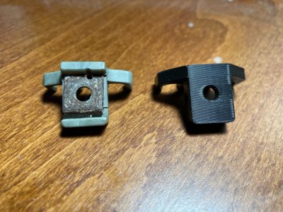
Alright, I had a few spare minutes this afternoon so I went and got one of the clips off my car (found out it's not in great shape too -- cracking in a few places :oops:
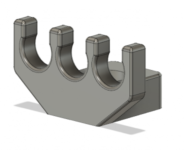
), measured it and sketched up a quick approximation in Fusion360. Attached is what I came up with.

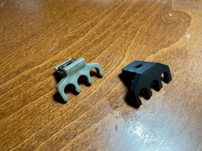
I forget how many different clips like this there are on the engine (maybe 3 or 4, each with a different number of wires clipped in it?), but I assume that if this one works out okay, the others could be made as well with just a little fiddling.

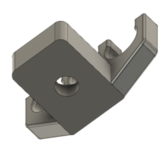
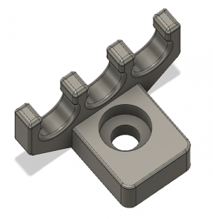
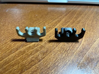
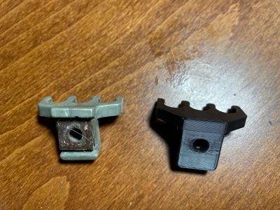
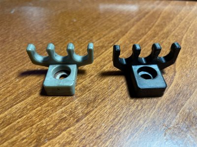
I'll probably print this out of PETG (EDIT: will be using ABS for the final prints for its higher heat resistance) in a bit and post some pics of the original and 3D printed side by side for comparison. The original does have a steel insert that ostensibly provides most of its strength, whereas my design is just printed all the way through, with a shouldered hole, hopefully providing enough strength with its slightly thicker thickness. If desired, I can cut a pocket out of the bottom of the design and a steel strip with a hole drilled in the center can be epoxied in place, providing at least as much strength as the original part.

@Deathacus -- would you be interested in something like this, or am I wasting my time :))... Actually, since I've discovered that at least one of my clips is cracked, I'll probably end up printing up a set for myself and I can share the STL files somehow later.

EDIT: Quick note, before someone else says it: I just realized that the stock part has a pocket in the bottom of it to accept the raised rectangular mounting boss of the valve covers -- I didn't include that in my design but I can put it in v2.
 

Attachments

  • image (5).png
    image (5).png
    98.6 KB · Views: 13
  • image (7).png
    image (7).png
    71 KB · Views: 11
  • image (6).png
    image (6).png
    169.1 KB · Views: 12
Last edited:

Deathacus

SHO Member
Joined
Jul 19, 2021
Messages
279
Reaction score
39
Location
Pennsylvania
Like, duuude! I am stoked to see the final product. I'm in no hurry if you think it needs some tweaks. But yeah, I figured all the plastic ones were getting brittle by now. I'd have to buy a set from you 'cause my folks wont let me make room for a printer :(
Thought about doing something like this when I was fixing the vent louvers that always seem to break.
 

jonheese

Used-To-Know-It-All
Joined
Oct 28, 2004
Messages
892
Reaction score
626
Location
Fogelsville, PA
Attached are some pics of my prototype clip alongside the (cracked) original part. The missing pocket from the underside is blatantly obvious to me now, but I will add it in the next iteration if there is interest. I confirmed that the original screw fits and should work well.

Speaking of which, the screw appears to be a #10-32 machine screw, about 3/8" long, but I haven't confirmed that with my thread checker yet.

I also haven't tried installing the new clip onto the valve cover nor popping the plug wires into it, but the dimensions are almost exactly the same, so I don't anticipate any problems there.
 

Attachments

  • IMG_3187.jpg
    IMG_3187.jpg
    334 KB · Views: 10
  • IMG_3191.jpg
    IMG_3191.jpg
    349.3 KB · Views: 10
  • IMG_3190.jpg
    IMG_3190.jpg
    380.7 KB · Views: 10
  • IMG_3189.jpg
    IMG_3189.jpg
    338.8 KB · Views: 10
  • IMG_3188.jpg
    IMG_3188.jpg
    340.4 KB · Views: 10

jonheese

Used-To-Know-It-All
Joined
Oct 28, 2004
Messages
892
Reaction score
626
Location
Fogelsville, PA
I should have some time tomorrow to get a second revision of the 3x clip and hopefully try it out on the car. You can juuuuust barely install/uninstall this one with the intake in place, but I haven't searched out the rest of the clips yet to see if they are similarly accessible. I will probably just go ahead and remove the intake to get the rest of the clips, but that probably won't happen until next weekend at the earliest.

One thing worth noting that I didn't mention before: I intentionally made the outermost "antlers" thicker on my part (you can see this best in the first comparison photo above) to try to give the part a little more strength in those areas, which I figured would be among the weakest. If anyone is not okay with that, you can import the STL files into your CAD app of choice and tweak them as desired. :biggrin:
 
Last edited:

Ta2dResqr

SHO Member
Joined
Dec 10, 2020
Messages
1,208
Reaction score
1,144
Location
Central Ohio
A couple suggestions. Try rotating the print 45*. Currently, the print lines are straight across causing a stress line and weak point most likely to separate at the widest point of the bolt hole. By rotating it, the diagonal will make the shortest length longer. The other option to prevent over-tightening and splitting it would be to enlarge the hole slightly and put a metal bushing inside the hole. The other suggestion is long term, you may want to look at ABS. PETG has a glass temperature of 50-85* C (122-185* F) depending on the grade/brand you are using. With engine bay temperatures, heat transfer from the motor, etc. you may start having issues over time or with extended use (engine on time).

The print looks awesome and I hope to see more of this type of stuff in the SHO community.
 

jonheese

Used-To-Know-It-All
Joined
Oct 28, 2004
Messages
892
Reaction score
626
Location
Fogelsville, PA
Great suggestions. I just printed the first test print from PLA because it's what was already on the printer. I thought PETG had a better heat resistance, but forgot about ABS. I have some ABS and have had good success printing with it in the past, so I'll definitely give that a whirl for the final product.

Good point about the angle of the layers too -- as I've implied, these are just test prints. I haven't really thought through all of the optimum settings for everything yet, but I definitely appreciate the feedback and will be sure to incorporate it into any final product.

I've been giving more thought to embedding a metal part as well, same as Ford did in the original part, and I like your idea about using a bushing to give a positive tightening stop without stressing the plastic.

Thanks again for your feedback and contributions! If this goes well, I think I'll make a new thread (sorry if I've hijacked your WTB thread, @Deathacus) to let folks know about the project.
 
Last edited:

jonheese

Used-To-Know-It-All
Joined
Oct 28, 2004
Messages
892
Reaction score
626
Location
Fogelsville, PA
I've posted a new thread to the "Gauging Interest" section for these clips -- so I can stop hijacking this thread now. :biggrin:


Forum statistics

Threads
107,085
Messages
1,181,297
Members
16,152
Latest member
lapochkarr

Members online

Back
Top