Matt M PA
SHO Member
- Joined
- Nov 5, 2017
- Messages
- 348
- Reaction score
- 245
I handled my DriveBright DRL installation over the weekend. While it took a bit longer than expected…no doubt due to my OCD…I’m pleased with the results. I thought it might be a good idea to pass along some of the things I did.
But first, a quick comment about Dan, from DriveBright. During my installation, I couldn't find the headlight wire required for the dimming circuit. I left a message realizing that I was past his normal business hours on a Saturday. Within minutes, a return phone call came and Dan gave me the information I needed. The car wasn't drivable as it was, so this was a huge help. Thanks Dan!
First, I found it helpful to remove each front wheel to allow better access into the front bumper. I also removed the lower splashpan for access from beneath. It's only a matter of five clips, and handful of screws, but I think it made the job much easier.
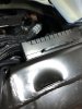
I also didn't like the idea of mounting the control box under the hood. I couldn't really find a spot I liked, and found a good spot on top of the driver’s side frame rail, towards the very end. This did require lengthening both the fuse tap wire for the courtesy light harness, as well as the power lead that went to the battery. I found a good ground point by loosening the bolt that holds the horns bracket, and placing the ground wire connection underneath that bolt
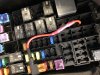
The fuse tap. Looking inside the fuse box, I can only assume that this fuse box is used for more cars than just the Taurus. There are many locations that are not used, and do not have a metal "circuit board" underneath. I passed the wire through one of the unused fuse holes and out the bottom. I thought this would make a more tidy installation.
I decided to run the wiring to the passenger side lamp across the front, above the radiator. There is other wiring in that location to which you can secure the harness. I should mention that I wrapped all harnesses and wires in convoluted wire loom. In my opinion, this not only protects the wire but also makes for more OEM look.
While some may choose to not use the dimming circuit, for those that do, the headlight wire is easily seen high up in the fender. It is visible when looking from inside the fender with the fender liner pulled back. (Thanks again for that, Dan.)
Finally, a word about removing the bezels. That was more difficult than I expected. I did figure 2 tricks that helped. (It’s important to know that the bezels have a number of tabs with a “wedge”. The pointy side of the wedge goes in first, and they retain the bezel with the flat side.) The first was to use a stubby, big bladed screwdriver to push the attaching tabs from the rear. However, a few wouldn't budge. I wound up taking a very small screwdriver, and pressed it between the bumper and the “wedge” part of the clip. Then, rotated the screwdriver down and pushed it slightly into the hole in the bumper. This seemed to help as it worked like a ramp to allow the tab to come out.
I also had an issue where something didn’t work. Turned out the tap wasn’t piercing the wire to which it was being connected.
On final note…the car has a clear bra and I had a few pieces of the material remaining. I trimmed a couple pieces and applied to the DRLs prior to install.
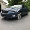
Wow…if you made it this far…thanks for reading. I hope it helps someone with their installation. I think these are a great upgrade that looks and works like it came from the factory.
But first, a quick comment about Dan, from DriveBright. During my installation, I couldn't find the headlight wire required for the dimming circuit. I left a message realizing that I was past his normal business hours on a Saturday. Within minutes, a return phone call came and Dan gave me the information I needed. The car wasn't drivable as it was, so this was a huge help. Thanks Dan!
First, I found it helpful to remove each front wheel to allow better access into the front bumper. I also removed the lower splashpan for access from beneath. It's only a matter of five clips, and handful of screws, but I think it made the job much easier.
I also didn't like the idea of mounting the control box under the hood. I couldn't really find a spot I liked, and found a good spot on top of the driver’s side frame rail, towards the very end. This did require lengthening both the fuse tap wire for the courtesy light harness, as well as the power lead that went to the battery. I found a good ground point by loosening the bolt that holds the horns bracket, and placing the ground wire connection underneath that bolt
The fuse tap. Looking inside the fuse box, I can only assume that this fuse box is used for more cars than just the Taurus. There are many locations that are not used, and do not have a metal "circuit board" underneath. I passed the wire through one of the unused fuse holes and out the bottom. I thought this would make a more tidy installation.
I decided to run the wiring to the passenger side lamp across the front, above the radiator. There is other wiring in that location to which you can secure the harness. I should mention that I wrapped all harnesses and wires in convoluted wire loom. In my opinion, this not only protects the wire but also makes for more OEM look.
While some may choose to not use the dimming circuit, for those that do, the headlight wire is easily seen high up in the fender. It is visible when looking from inside the fender with the fender liner pulled back. (Thanks again for that, Dan.)
Finally, a word about removing the bezels. That was more difficult than I expected. I did figure 2 tricks that helped. (It’s important to know that the bezels have a number of tabs with a “wedge”. The pointy side of the wedge goes in first, and they retain the bezel with the flat side.) The first was to use a stubby, big bladed screwdriver to push the attaching tabs from the rear. However, a few wouldn't budge. I wound up taking a very small screwdriver, and pressed it between the bumper and the “wedge” part of the clip. Then, rotated the screwdriver down and pushed it slightly into the hole in the bumper. This seemed to help as it worked like a ramp to allow the tab to come out.
I also had an issue where something didn’t work. Turned out the tap wasn’t piercing the wire to which it was being connected.
On final note…the car has a clear bra and I had a few pieces of the material remaining. I trimmed a couple pieces and applied to the DRLs prior to install.
Wow…if you made it this far…thanks for reading. I hope it helps someone with their installation. I think these are a great upgrade that looks and works like it came from the factory.